Connect and select
Use TRS key wiring and an external keyer if using a paddle.
Hermes-Lite 2 is a network SDR project available as manufacturer-built hardware. A working station also needs the appropriate filter board, power, enclosure and computer setup. This guide uses the project-linked Thetis workflow and keeps external-keyer responsibilities explicit.
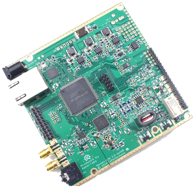
Project External Connections and Thetis Setup wiki; Thetis installation guide v9, 14 May 2024; confirm gateware and Thetis build. Checked 2026-10-04; base-board project gateware; optional Companion/I/O boards excluded. v9 pp. 3–6, 8–10, 61–62 and current project wiki sections; author examples are not factory defaults.
Use this order as an operating checklist, not as a replacement for the radio manual. Controls and available options can vary by firmware and region.
Use TRS key wiring and an external keyer if using a paddle.
Confirm filter-board routing and a dummy load before enabling RF.
Set external keyer speed and local sidetone; verify PC receive audio.
Discover the radio in Thetis and tune a clear CW signal.
Check TX frequency, drive and PTT release; then operate with the intended antenna.
Search by setting or menu path. Manufacturer defaults and recommendations are labeled separately from CW599 advice; references identify the checked manual or software version.
CN4: tip KEY / ring PTTCW599 note: CN4 takes a 3.5 mm stereo TRS plug: tip is KEY, ring is PTT and sleeve is ground. The base hardware has no internal paddle keyer or sidetone. Connect a straight key or an external keyer with local monitoring. A mono plug grounds the ring and can hold transmit. Check contact release into a dummy load at low power.
Manual reference: External Connections: CN4; Thetis v9, p. 61
Setup > General > H/W Select > Radio ModelCW599 note: Use the Hermes-Lite-compatible Thetis build linked by the project and follow that release’s installation notes. Select HERMES LITE and your actual Region, then Apply. Confirm the detected radio and version. The manual’s IP addresses, region and optional HL2 I/O Board checkbox are examples, not universal defaults. This guide covers the base board, not an add-on keyer.
Ethernet; Thetis radio discoveryCW599 note: Connect Ethernet and verify that Thetis discovers the intended radio before diagnosing CW. A direct PC connection needs the project’s network procedure. If discovery fails, check the cable, power and local network configuration; changing keyer speed or copying the manual’s example IP will not solve a missing radio.
Setup > General > OC Control > N2ADR Filter; ANTCW599 note: For the N2ADR board, use N2ADR Filter to load its pin mapping. Change bands while receiving and inspect Hardware Pin State. Use the assembled station’s filtered main ANT path; RF1 is a low-level output, not an interchangeable antenna socket. The PA Enable and drive settings must match the actual hardware. Do not copy the author’s maximum-power example for a first CW test.
Manual reference: Thetis v9, pp. 8–10; External Connections: RF1 / RF3
Thetis console: CW mode / receive filterCW599 note: Select CW, tune one clear signal and inspect the receive passband. Narrow gradually while keeping that signal audible. Before answering, read the transmit frequency and any split state separately. If the signal disappears, widen the filter and retune; filter settings do not add received-text decoding.
Setup > Audio > VAC1; external keyer monitorCW599 note: The project’s setup enables VAC1 for PC receive audio. Choose the actual audio device and confirm a received signal is audible. For paddle timing use the external keyer’s local sidetone. The software Sidetone checkbox is not evidence of a sidetone generator in the base board; PC audio can add delay. If silent, check device selection, mute and volume one at a time.
Manual reference: Thetis Setup wiki: Audio; Thetis v9, p. 61
External keyer: speed / monitorCW599 note: Set paddle speed on the external keyer and listen locally. Check complete dots, dashes and spaces into a dummy load at low power. The page-62 example uses a Companion board for paddle monitoring: that optional board is outside this base-hardware guide. Changing a Thetis speed field does not add a hardware paddle keyer to CN4.
Manual reference: External Connections: CN4; Thetis v9, pp. 61–62
Setup > DSP > CW > CW Break-in; CN4 PTTCW599 note: Thetis shows SEMI and Delay (ms) in DSP > CW. Start conservatively and verify that the first element is intact and receive returns after release. Gateware 71p2 introduced combined ring-PTT/tip-key operation; earlier versions behave differently. Match the installed gateware and external keyer. COM9/RTS, pitch 650 and delay 306 in the screenshot are examples, not settings to copy for every station.
Manual reference: External Connections: CN4; Thetis v9, p. 61
No matching settings. Try a shorter search or clear the search and category.
These are original operator-oriented starting points. They are not factory presets and intentionally avoid claiming model-specific default values.
Check one change at a time.
Keep the wanted signal audible.
Leave a clear path back to receiving.
The checked documentation does not provide a built-in received-CW text workflow for Hermes-Lite 2 hardware. Any received-text decoder belongs to separately selected PC software.
CN4 is KEY/PTT, not an internal paddle-keyer input. Use an external keyer and the documented tip/ring wiring.
A mono plug can ground the PTT ring. Disconnect and inspect the TRS wiring before changing software timing.
Use the manufacturer-controlled product and support pages to verify your region, firmware, menus, connector wiring, operating limits, and safety information. CW599 does not host, mirror, or reproduce the manual.
Search and filters run locally in your browser and do not connect to a radio. Version 1.0 (2026-10-04): four-language guide and sourced product photo. Revisions are retained in site Git and release backups; no separate archived page.